Adjustable Radiator Fan Wiring Diagram Fan Control A Flex - Jika kamu mencari artikel Adjustable Radiator Fan Wiring Diagram Fan Control A Flex terlengkap, berarti kamu sudah berada di blog yang benar. Setiap artikel dibahas secara mendetail dengan penyajian bahasa yang enteng dipahami bagi orang awam sekalipun. itulah sebabnya situs ini banyak diminati para blogger dan pembaca online. Yuk langsung saja kita simak pembahasan Adjustable Radiator Fan Wiring Diagram Fan Control A Flex berikut ini.
Adjustable Radiator Fan Wiring Diagram Fan Control A Flex. Part number 31149 Temp. Assortment of flex a lite fan controller wiring diagram. Wire the fan motor s refer to above wiring diagram. And we proudly make our products in the US. Connect the motor wires to the control module Red wire to the M terminal and black wire to the M- terminal.
F250 Wiring Diagram Perhaps one of the least understood parts of adding an electric fan to a vehicle is installing and wiring the controller. Flex A Lite Fan Controller Wiring Diagram wiring diagram is a simplified all right pictorial representation of an electrical circuit. Electronics - Wiring electric fan with HAYDEN sensor - Hi Everyone. The controller can be used with single or dual fan setups. Turning the vehicle power on will automatically turn on the fan control-ler and the red digital display will light up. The inlet hose as possible then push the rubber insulator cap.
Using a Blue Butt.
Sbc With Hei Wiring Diagram ADJUSTABLE ELECTRIC FAN CONTROLLER PART 16749 KIT CONTENTS QTY. Suggested Primary Cooling Fan - Single Speed ONOFF NOTE. 86 graywhite wire goes to the ignition switch. Red Wire 3 10 Sheet Metal Screws QTY. Part number 31149 Temp. Using a Blue Butt Connector provided attach the Orange wire to the Positive electric fan lead.
Part number 31149 Temp.
1996 Ezgo Gas Electrical Diagrams 30 other red wire needs constant 12-volt power from the battery. DESCRIPTION 1 Fan Control Module 1 4060 Amp Relay 1 Wire harness with 38 NPT Thread-in Probe 1 5 12Ga. 86 graywhite wire goes to the ignition switch. Turning the vehicle power on will automatically turn on the fan control-ler and the red digital display will light up. Most stand-alone adjustable thermostats ie.
Wiring Dual Cooling Fans.
Cal Spa 2100 Diagram Fan 2 Blue Wire. And we proudly make our products in the US. Complete kit includes adjustable temperature control 2 capillary tube wire terminals and instructions. A helpful diagram I found for wiring this Hayden fan switch because the. The full product line now includes the patented Flex-a-fit aluminum radiators electric fans belt-driven fans oil coolers Mojave heaters and Flexite windows. DESCRIPTION 1 Fan Control Module 1 4060 Amp Relay 1 Wire harness with 38 NPT Thread-in Probe 1 5 12Ga.
Be sure to use wire that is intended to handle the current amp rating of the fan.
Xiaomi Redmi 4a Schematic Diagram Disconnect the negative battery lead for safety while finishing the wiring. Most stand-alone adjustable thermostats ie. Performance cooling products for the automotive market. Just turn a knob to change activating temperature from 180-240 F. Control Module Wiring Diagram 1a.
Most stand-alone adjustable thermostats ie.
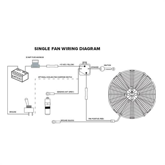
Volvo 850 Engine Diagram Flex-a-lite invented the Flex Fan and holds the patent for the first electric fan for the automotive aftermarket. Diagram 4 Diagram 3 30amp Fuse Red Wire Battery Power 12V Black Wire Chassis Ground - Green Wire Optional AC Override One Way Diode Orange Wire Positive Fan Lead Blue Wire Optional Secondary Fan Positive Lead Yellow Wire to. It shows the components of the circuit as simplified shapes and the capability and signal associates. With dual cooling fans there are two methods for wiring up the relay kit. Please see the wiring diagram for more information. Compact Adjustable Electric Fan Controller with Relay Kit These new Flex-A-Lite electric fan controllers pack a lot of features into a small package.
Connect the fan motor wires to the control module positive wire to the M terminal and negative motor wire to the M- terminal.
Data Flow Diagram Of Manual Library System My question is how do I wire in my electric fan control thermostat unit into my The non adjustable one is about 30 Hayden and the Note that the thermostat switch in the diagram isnt really suited for the job. 86 graywhite wire goes to the ignition switch. My question is how do I wire in my electric fan control thermostat unit into my The non adjustable one is about 30 Hayden and the Note that the thermostat switch in the diagram isnt really suited for the job. The full product line now includes the patented Flex-a-fit aluminum radiators electric fans belt-driven fans oil coolers Mojave heaters and Flexite windows. Connect the fan motor wires to the control module positive wire to the M terminal and negative motor wire to the M- terminal.
Using a Blue Butt Connector provided attach the Orange wire to the Positive electric fan lead.
197Corvette Dash Wiring Diagram ADJUSTABLE ELECTRIC FAN CONTROLLER PART 16749 KIT CONTENTS QTY. Connect the motor wires to the control module Red wire to the M terminal and black wire to the M- terminal. Hayden Flex-a-Lite or Perma-Cool brands can provide a 12 volt output when activated. 85 black wire. Suggested Electric Fan Wiring Diagrams Suggested Primary Cooling Fan - Single Speed ONOFF Using 12 Volt Switching Devices Only for Primary Activation NOTE. Diagram 4 Diagram 3 30amp Fuse Red Wire Battery Power 12V Black Wire Chassis Ground - Green Wire Optional AC Override One Way Diode Orange Wire Positive Fan Lead Blue Wire Optional Secondary Fan Positive Lead Yellow Wire to.
February 16 2019 by Larry A.
Dc Shunt Winch Motor Wiring Diagram Suggested Primary Cooling Fan - Single Speed ONOFF NOTE. Lead on electric fan unit. Diagram 2 Control Module Wiring Continues on reverse side. A wiring diagram is a simplified traditional pictorial depiction of an electrical circuit. Disregard cut any exposed copper and tape or shrink wrap the end of the wire.
87 red wire connects to the positive wire on the electric fan.
Wiring Diagram For A House The inlet hose as possible then push the rubber insulator cap. The inlet hose as possible then push the rubber insulator cap. ADJUSTABLE ELECTRIC FAN CONTROLLER PART 16749 KIT CONTENTS QTY. Connect the C terminal on the control unit to the positive. Turning the vehicle power on will automatically turn on the fan control-ler and the red digital display will light up. Suggested Electric Fan Wiring Diagrams Suggested Primary Cooling Fan - Single Speed ONOFF Using 12 Volt Switching Devices Only for Primary Activation NOTE.
Compact Adjustable Electric Fan Controller with Relay Kit These new Flex-A-Lite electric fan controllers pack a lot of features into a small package.
System Sensor Smoke Detector Wiring Diagram ADJUSTABLE ELECTRIC FAN CONTROLLER PART 16749 KIT CONTENTS QTY. Compact Adjustable Electric Fan Controller with Relay Kit These new Flex-A-Lite electric fan controllers pack a lot of features into a small package. Please see the wiring diagram for more information. Wire the fan motor s refer to above wiring diagram. Using a Blue Butt Connector provided attach the Orange wire to the Positive electric fan lead.
Flex-a-lite invented the Flex Fan and holds the patent for the first electric fan for the automotive aftermarket.
2000 Bmw 323i Fuse Box Diagram Lead on electric fan unit. Just turn a knob to change activating temperature from 180-240 F. Fan 2 Blue Wire. Suggested Primary Cooling Fan - Single Speed ONOFF NOTE. Use the 3 mounting screws provided. DESCRIPTION 1 Fan Control Module 1 4060 Amp Relay 1 Wire harness with 38 NPT Thread-in Probe 1 5 12Ga.
My question is how do I wire in my electric fan control thermostat unit into my The non adjustable one is about 30 Hayden and the Note that the thermostat switch in the diagram isnt really suited for the job.
The Impeachment Plot Revealing The Secrets Lies And Political Schemes To Unseat The President February 16 2019 by Larry A. Fan 2 Blue Wire. This is based on the draw from the fans if the fans are larger and draw more than 15 amps each its recommended to install a second relay kit as shown below. It reveals the elements of the circuit as streamlined forms as well as the power and also signal links in between the devices. Turning the vehicle power on will automatically turn on the fan control-ler and the red digital display will light up.
It reveals the elements of the circuit as streamlined forms as well as the power and also signal links in between the devices.
Seeing Reason Diagrams And Languages In Learning To Think Wiring Dual Cooling Fans. And we proudly make our products in the US. My question is how do I wire in my electric fan control thermostat unit into my The non adjustable one is about 30 Hayden and the Note that the thermostat switch in the diagram isnt really suited for the job. The full product line now includes the patented Flex-a-fit aluminum radiators electric fans belt-driven fans oil coolers Mojave heaters and Flexite windows. Radiator Adjustable Variable Speed Fan Controller cont. Suggested Primary Cooling Fan - Single Speed ONOFF NOTE.
Control Module Wiring Diagram 1a.
97 Chrysler Cirrus Engine Diagram Lead on electric fan unit. You may want to mount next to radiator on fender well. The inlet hose as possible then push the rubber insulator cap. Most stand-alone adjustable thermostats ie. This kit lets you make any electric fan thermostatically controlled.
Flex-a-lite invented the Flex Fan and holds the patent for the first electric fan for the automotive aftermarket.
Analytical Diagram Cord Turning the vehicle power on will automatically turn on the fan control-ler and the red digital display will light up. Most stand-alone adjustable thermostats ie. Complete kit includes adjustable temperature control 2 capillary tube wire terminals and instructions. It shows the components of the circuit as simplified shapes and the capability and signal associates. You may want to mount next to radiator on fender well. Using a Blue Butt Connector provided attach the Orange wire to the Positive electric fan lead.
Connect the fan motor wires to the control module positive wire to the M terminal and negative motor wire to the M- terminal.
Mach3 Cnc Wiring Diagram Wiring Dual Cooling Fans. A helpful diagram I found for wiring this Hayden fan switch because the. Over the end of the sensor as shown. Be sure to use wire that is intended to handle the current amp rating of the fan. Diagram 2 Control Module Wiring Continues on reverse side.
Situs ini adalah komunitas terbuka bagi pengguna untuk membagikan apa yang mereka cari di internet, semua konten atau gambar di situs web ini hanya untuk penggunaan pribadi, sangat dilarang untuk menggunakan artikel ini untuk tujuan komersial, jika Anda adalah penulisnya dan menemukan gambar ini dibagikan tanpa izin Anda, silakan ajukan laporan DMCA kepada Kami.
Jika Anda menemukan situs ini bermanfaat, tolong dukung kami dengan membagikan postingan ini ke akun media sosial seperti Facebook, Instagram dan sebagainya atau bisa juga simpan halaman blog ini dengan judul Adjustable Radiator Fan Wiring Diagram Fan Control A Flex dengan menggunakan Ctrl + D untuk perangkat laptop dengan sistem operasi Windows atau Command + D untuk laptop dengan sistem operasi Apple. Jika Anda menggunakan smartphone, Anda juga dapat menggunakan menu laci dari browser yang Anda gunakan. Baik itu sistem operasi Windows, Mac, iOS, atau Android, Anda tetap dapat menandai situs web ini.