Block Diagram Summing Junction - Jika kamu mencari artikel Block Diagram Summing Junction terbaru, berarti kamu sudah berada di blog yang benar. Setiap artikel diulas secara mendetail dengan penyajian bahasa yang ringan dipahami bagi orang awam sekalipun. itulah sebabnya situs ini banyak diminati para blogger dan pembaca online. Yuk langsung saja kita simak ulasan Block Diagram Summing Junction berikut ini.
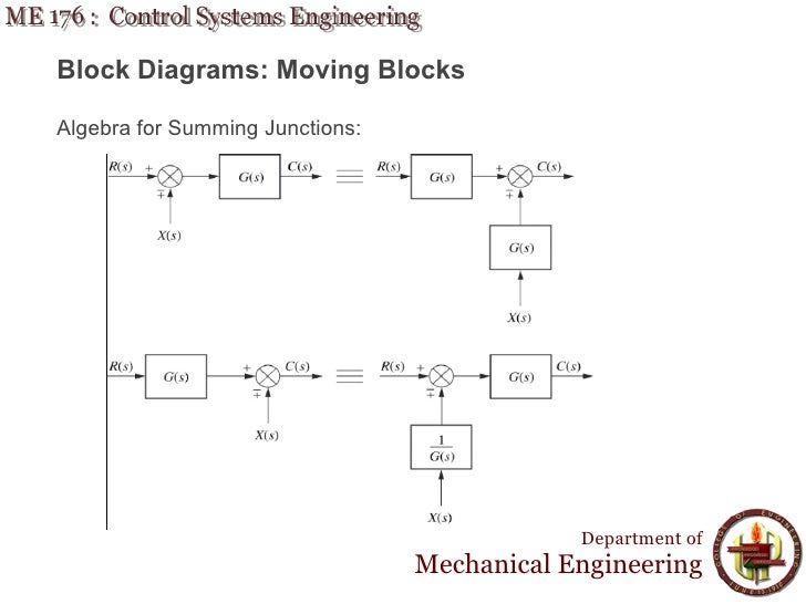
Block Diagram Summing Junction. Output of this block diagram is - YsGsRsXs Equation 3 Now shift the summing point before the block. The logical Summing Junction flowchart shape is shows when multiple branches converge into a single process. This block diagram is shown in the following figure. The basic elements of a block diagram are a block the summing point and the take-off point. You can also include one or more summing junction that you create using sumblk.
1998 Mercedes E320 Wiring Diagram Brakes Consider the block diagram shown in the following figure. The above block diagram consists of two blocks having transfer functions G s and H s. Shift the input of B to the left before the summing junction. Block Diagram Reduction Rules - Casacde Parallel Moving Pickoff Summing PointsFor Students of BTech BE MCA BCA BSc MSc Courses - As Per IP Uni. Called a summing point. Here the summing point is present after the block.
Which of the following symbols in a block diagram represents a summing junction.
Circuit Diagram Components The function of a block diagram is to simplify a very complex system to its most fundamental components. Moving a summing point beyond of a block. Rearrangement of summing points. The current practice in the simplification of block diagrams using block diagram algebra. You can also include one or more summing junction that you create using sumblk. The merge symbol is more common for this use though.
A block diagram provides a means to easily identify the functional relationships among the various components of a control system.
Beckett Pump Wiring Diagram 4 Now we have one simple forward path ED in parallel to C resulting in CDE and two simple negative feedback loops which can be solved separately Blacks formula. Block Diagram Algebra Often want to simplify block diagrams into simpler recognizable forms To determine the equivalent transfer function Simplify to instances of the three standard forms then simplify those forms Move blocks around relative to summing junctions. Block diagram Summing junction Output signal C s is the algebraic sum of the input signals R1 s R2 s and R3 s. But as we also know that the block diagram representation of a system involves summing points functional blocks and take-off points connected through branches and flow of signal shown by the arrowheads. The current practice in the simplification of block diagrams using block diagram algebra.
Shifting Summing Point Before the Block.
Vs Calais Stereo Wiring Diagram Block diagram Summing junction Output signal C s is the algebraic sum of the input signals R1 s R2 s and R3 s. The equivalency of summing junction in series to mathematical summer is self-explanatory. Consider the block diagram shown in the following figure. The basic elements of a block diagram are a block the summing point and the take-off point. Block diagrams 4 summing junctions SUMMING JUNCTIONS ARE NEEDED FOR FEEDBACK AND WHERE WE NEED ADDITION OR SUBTRACTION OF SIGNALS. Block diagram elements can also include a pid or tunablePID model representing a controller.
The merge symbol is more common for this use though.
1998 Navigator Fuse Box Diagram Consider the block diagram shown in the following figure. Shifting Summing Point Before the Block. Moving a summing point beyond of a block. Provide multiple arguments sys1sysN to represent all of the block diagram elements and summing junctions. Which of the following symbols in a block diagram represents a summing junction.
Output of this block diagram is -.
Trailer Wiring Diagram 2012 Hyundai Moving a summing point beyond of a block. Consider the block diagram shown in the following figure. Block Diagram Algebra Often want to simplify block diagrams into simpler recognizable forms To determine the equivalent transfer function Simplify to instances of the three standard forms then simplify those forms Move blocks around relative to summing junctions and pickoff points simplify to a standard form. We assume readers are now comfortable with transfer function representations and seriesparallel arrangements. Which of the following symbols in a block diagram represents a transfer function. It is necessary to indicate the fine specifying the input signal entering a summing point in the block diagram of control system.
Consider the block diagram shown in the following figure.
Toyota Xli Electrical Wiring Diagram Block diagram elements can also include a pid or tunablePID model representing a controller. Block diagrams 4 summing junctions SUMMING JUNCTIONS ARE NEEDED FOR FEEDBACK AND WHERE WE NEED ADDITION OR SUBTRACTION OF SIGNALS. Output of this block diagram is - YsGsRsXs Equation 3 Now shift the summing point before the block. Which of the following symbols in a block diagram represents a transfer function. A block diagram is a pictorial representation of the cause and effect relationship between the input and output of a physical system.
Output of this block diagram is - YsGsRsXs Equation 3 Now shift the summing point before the block.
Kawasaki Klr650 Color Wiring Diagram Kl600a Klr 600 Drehzahlmesser A block diagram provides a means to easily identify the functional relationships among the various components of a control system. The merge symbol is more common for this use though. Consider the block diagram shown in the following figure. But as we also know that the block diagram representation of a system involves summing points functional blocks and take-off points connected through branches and flow of signal shown by the arrowheads. Output of this block diagram is - YsGsRsXs Equation 3 Now shift the summing point before the block. Shift the input of B to the left before the summing junction.
The function of a block diagram is to simplify a very complex system to its most fundamental components.
Tone Saver Wiring Diagram Fender Shift the input of B to the left before the summing junction. The basic elements of a block diagram are a block the summing point and the take-off point. Let us take an example. Now this block must have the function B-D instead of B only. Provide multiple arguments sys1sysN to represent all of the block diagram elements and summing junctions.
The merge symbol is more common for this use though.
1996 V6 Vortec Engine Diagram Which of the following symbols in a block diagram represents a summing junction. But as we also know that the block diagram representation of a system involves summing points functional blocks and take-off points connected through branches and flow of signal shown by the arrowheads. The function of a block diagram is to simplify a very complex system to its most fundamental components. Which of the following symbols in a block diagram represents a transfer function. Output of this block diagram is -. This symbol and the Or symbol are really more relevant in data processing flow diagrams than in process flowcharts.
Block Diagram Reduction Rules - Casacde Parallel Moving Pickoff Summing PointsFor Students of BTech BE MCA BCA BSc MSc Courses - As Per IP Uni.
2004 Ford Star Ac Wiring Diagram Let us consider the block diagram of a closed loop control system as shown in the following figure to identify these elements. This symbol and the Or symbol are really more relevant in data processing flow diagrams than in process flowcharts. Block diagram elements can also include a pid or tunablePID model representing a controller. It is necessary to indicate the fine specifying the input signal entering a summing point in the block diagram of control system. The equivalency of summing junction in series to mathematical summer is self-explanatory.
Block diagram elements can also include a pid or tunablePID model representing a controller.
Honda Cr250 Engine Diagram The above block diagram consists of two blocks having transfer functions G s and H s. This symbol and the Or symbol are really more relevant in data processing flow diagrams than in process flowcharts. Consider the block diagram shown in the following figure. Now this block must have the function B-D instead of B only. The basic elements of a block diagram are a block the summing point and the take-off point. Block Diagram Algebra Often want to simplify block diagrams into simpler recognizable forms To determine the equivalent transfer function Simplify to instances of the three standard forms then simplify those forms Move blocks around relative to summing junctions.
Interchange of summing points.
87 Corvette Dashboard Wiring Diagram Free Download Using the block diagram reduction technique find the transfer function of the control system represented by the following block diagram. Block Diagram Reduction Rules - Casacde Parallel Moving Pickoff Summing PointsFor Students of BTech BE MCA BCA BSc MSc Courses - As Per IP Uni. A block diagram provides a means to easily identify the functional relationships among the various components of a control system. This symbol and the Or symbol are really more relevant in data processing flow diagrams than in process flowcharts. The above block diagram consists of two blocks having transfer functions G s and H s.
We assume readers are now comfortable with transfer function representations and seriesparallel arrangements.
Opal Astra 1999 Wiring Diagram Za Pickoff point Distributes the input signals R s undiminished to several output points. Block diagram elements can also include a pid or tunablePID model representing a controller. Block Diagram Algebra Often want to simplify block diagrams into simpler recognizable forms To determine the equivalent transfer function Simplify to instances of the three standard forms then simplify those forms Move blocks around relative to summing junctions. Output of this block diagram is - YsGsRsXs Equation 3 Now shift the summing point before the block. Consecutive Summing Point A summing point with more than two inputs can be divided into two or more consecutive summing points where alteration of the position of consecutive summing points does not affect the output of the signal. YsGsUs is equivalent to Example with a summing junction.
Block diagram elements can also include a pid or tunablePID model representing a controller.
1996 Toyota Corolla Starting And Charging Systems Diagrams A block diagram provides a means to easily identify the functional relationships among the various components of a control system. Pickoff point Distributes the input signals R s undiminished to several output points. 4 Now we have one simple forward path ED in parallel to C resulting in CDE and two simple negative feedback loops which can be solved separately Blacks formula. This symbol and the Or symbol are really more relevant in data processing flow diagrams than in process flowcharts. Thus it is always better to draw the block diagram of the system in the easiest possible way thereby making the analysis simple.
Block Diagram Reduction Rules - Casacde Parallel Moving Pickoff Summing PointsFor Students of BTech BE MCA BCA BSc MSc Courses - As Per IP Uni.
Chevelle Ignition Switch Wiring Diagram Using the block diagram reduction technique find the transfer function of the control system represented by the following block diagram. But as we also know that the block diagram representation of a system involves summing points functional blocks and take-off points connected through branches and flow of signal shown by the arrowheads. A block diagram provides a means to easily identify the functional relationships among the various components of a control system. YsGsUs is equivalent to Example with a summing junction. Shift the input of B to the left before the summing junction. The logical Summing Junction flowchart shape is shows when multiple branches converge into a single process.
A block diagram provides a means to easily identify the functional relationships among the various components of a control system.
98 Ford F 150 Fuse Diagram Summing junction in series is crucial in the simpli-fication of some block diagrams. Summing points in series can be interchanged combined and separ-ated algebraically. It is necessary to indicate the fine specifying the input signal entering a summing point in the block diagram of control system. The basic elements of a block diagram are a block the summing point and the take-off point. Summing junction in series is crucial in the simpli-fication of some block diagrams.
Situs ini adalah komunitas terbuka bagi pengguna untuk menuangkan apa yang mereka cari di internet, semua konten atau gambar di situs web ini hanya untuk penggunaan pribadi, sangat dilarang untuk menggunakan artikel ini untuk tujuan komersial, jika Anda adalah penulisnya dan menemukan gambar ini dibagikan tanpa izin Anda, silakan ajukan laporan DMCA kepada Kami.
Jika Anda menemukan situs ini baik, tolong dukung kami dengan membagikan postingan ini ke akun media sosial seperti Facebook, Instagram dan sebagainya atau bisa juga save halaman blog ini dengan judul Block Diagram Summing Junction dengan menggunakan Ctrl + D untuk perangkat laptop dengan sistem operasi Windows atau Command + D untuk laptop dengan sistem operasi Apple. Jika Anda menggunakan smartphone, Anda juga dapat menggunakan menu laci dari browser yang Anda gunakan. Baik itu sistem operasi Windows, Mac, iOS, atau Android, Anda tetap dapat menandai situs web ini.